FEATURES OF THE CENTRIFUGAL PUMP

Each centrifugal pump has its own characteristic curve, which is the graphical representation of the pump's performance.

  • On the x-axis (horizontal axis) is reported the flow rate Q, usually in m3/h. It indicates the amount of fluid that passes through each section of the centrifugal pump over a defined period. This quantity depends on the dimensional characteristics of the pump, the number of motor revolutions (i.e., the speed of rotation of the impeller), and the characteristics of the fluid (density and viscosity depending on the temperature). The flow rate affects all the performances of the centrifugal pump and is the first technical parameter to consider.
  • On the y-axis (vertical axis) is instead reported the head H, usually in meters. It is calculated from the pressure difference between the outlet and the inlet of the centrifugal pump and represents how far the fluid can be pushed if it encounters resistance along its path, such as height, curves, or valves.

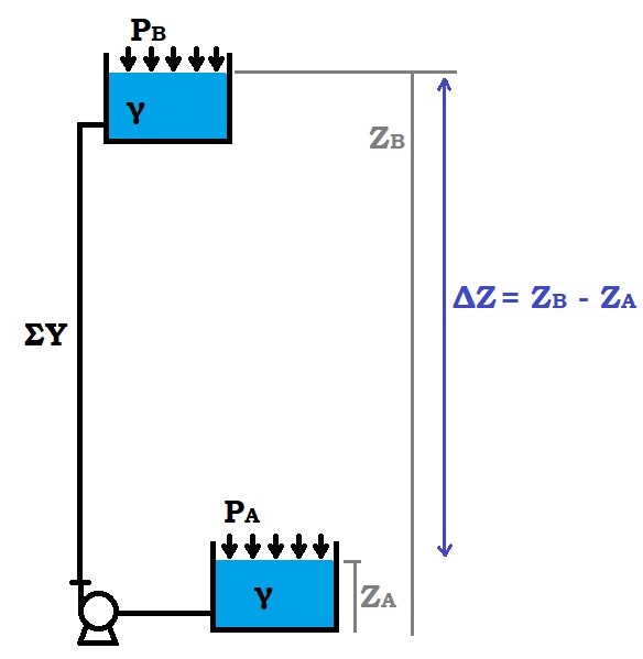
Let's define:
  • ΔZ the height difference between the lower basin A and the upper basin B;
  • PA and PB are the pressures acting
    respectively on the free surface of the upper basin A and the free surface of the upper basin
    B;
  • γ = specific weight of the fluid (= fluid density*gravity acceleration g);
  • ΣY the sum of distributed and localized losses
    within the system.
1895-Dragon

In ideal conditions, with perfectly smooth conduits, without curves, valves or filters, thus
ΣY = 0 and with PA = PB = ambient pressure, we would have that H = ΔZ, so the centrifugal pump provides all the energy to overcome only the height.
In reality, the pump must overcome more than just the height difference as ideal conditions can never be reached, so the head that must be achieved is
H = ΔZ + (PB - PA)γ + ΣY

Once the dimensions of the centrifugal pump (impeller and volute) and the speed of rotation of the impeller (given by the motor's RPM) are established, the characteristic curve is unique and typical for each pump.

CENTRIFUGAL PUMP

Knowing the specific weight of the fluid γ, it's also possible to calculate the theoretical power W, in Watts, required to move it:

W = γ ⋅ Q ⋅ H
For magnetically driven centrifugal pumps, the magnetic torque needed to move the fluid must also be considered.
The actual power Wa absorbed by the motor is slightly greater as we must account for friction and fluid dynamic losses within the pump itself, which are considered in the efficiency η. The power curve, always in relation to the flow rate Q, therefore refers to the following formula
Wa = W/η
It is intuitive to understand that as the flow rate increases, the required power will also increase, as shown in the graph below.

CENTRIFUGAL PUMP
Ask for information

Are you interested in Fluimac services?
Fulfil the below form and we'll reply as soon as possible.

Sign up to our Newsletter